Last Updated: October 14, 2020
- How to install the software on the Esp32
- How to configure your pylon as a gateway – so devices can connect over WIFI (instead of directly to the pylon)
- Cases for your Esp 32
- How to build an Arduino-based pylon and install & configure its software
How to install the software on the Esp32
Here are some part lists for building “pylons” (A pylon is: a LoRa receiver/transmitter – whether it lives on a rooftop or in your pocket) – to build your own network
1. Plug your esp32 into the computer
2. Download the Arduino SDK from: arduino.cc/en/Main/Software and Install it on your computer (PC or Mac)
Note: You will also need to download and unzip our LoRa software. Setting it up is explained in detail in Step 9.
3. Open it and go to “Preferences” and cut and paste this URL into the “Additional Board Manager URLS” form field:
https://dl.espressif.com/dl/package_esp32_index.json
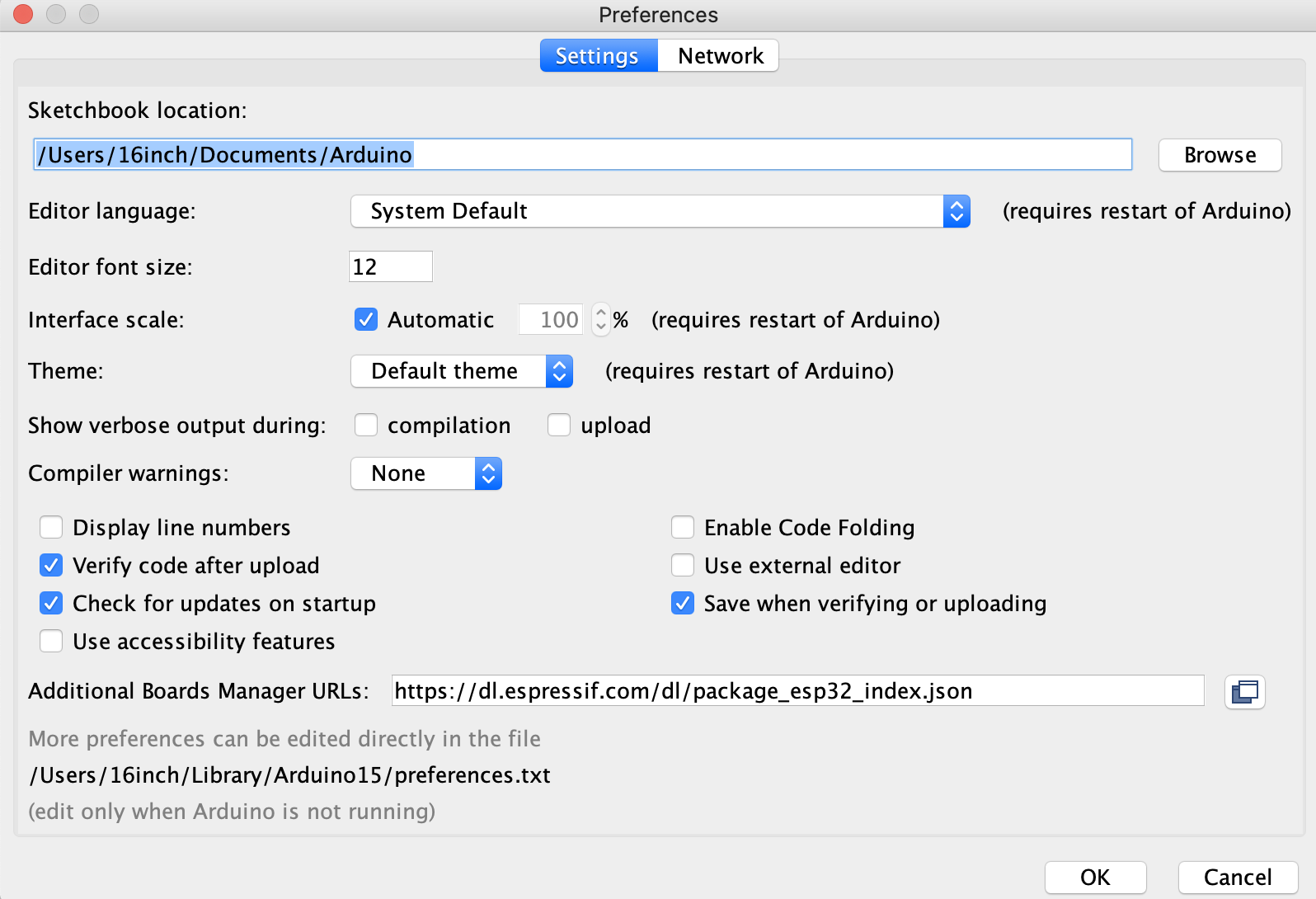
4. Click OK and close & restart the program
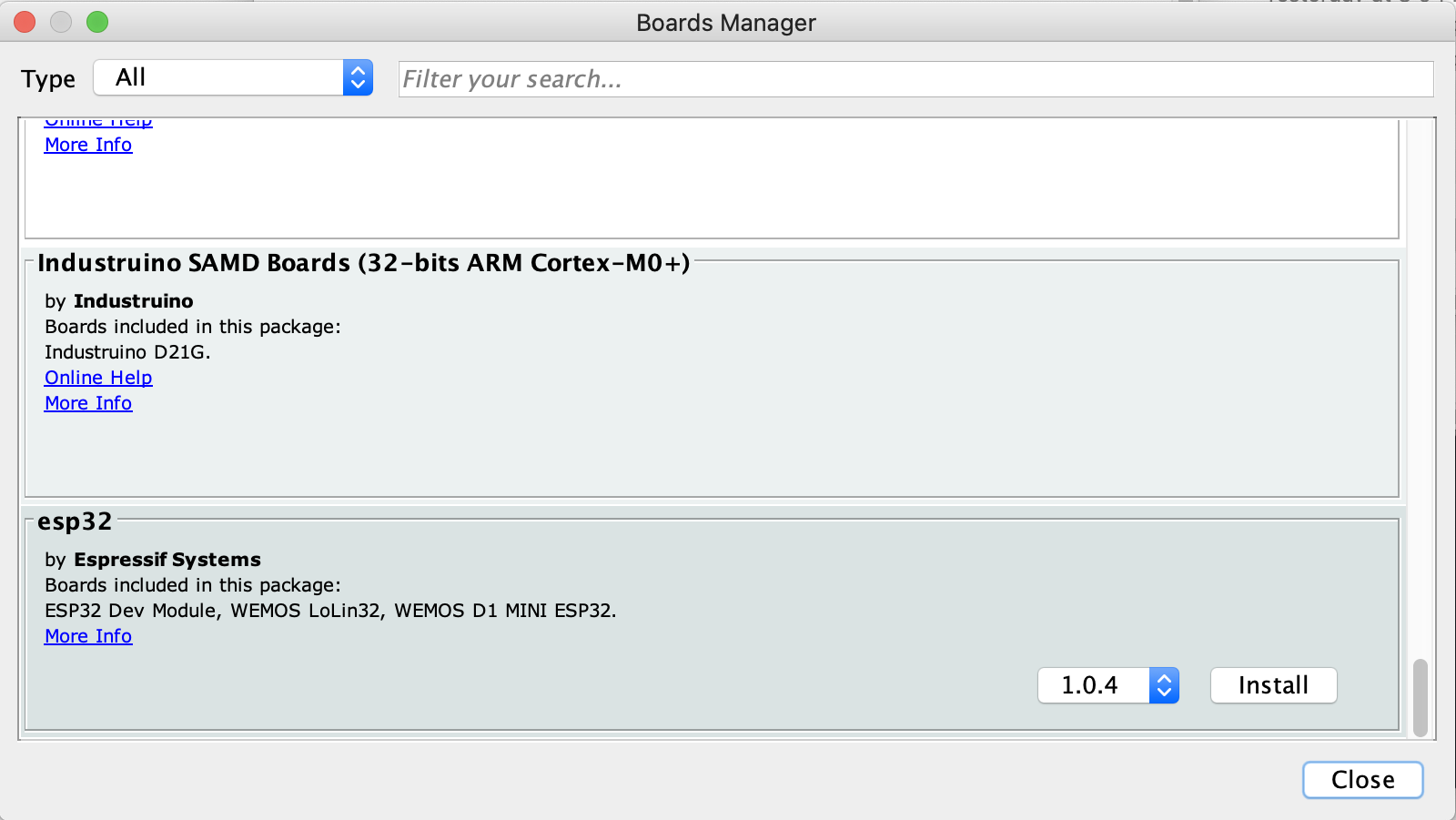
5. Go to “Tools”
“Board”
“Board Manager”
SCREENGRAB SELECTING THIS
and scroll to the very bottom where it says esp32 by Espressif Systems – and install those libraries
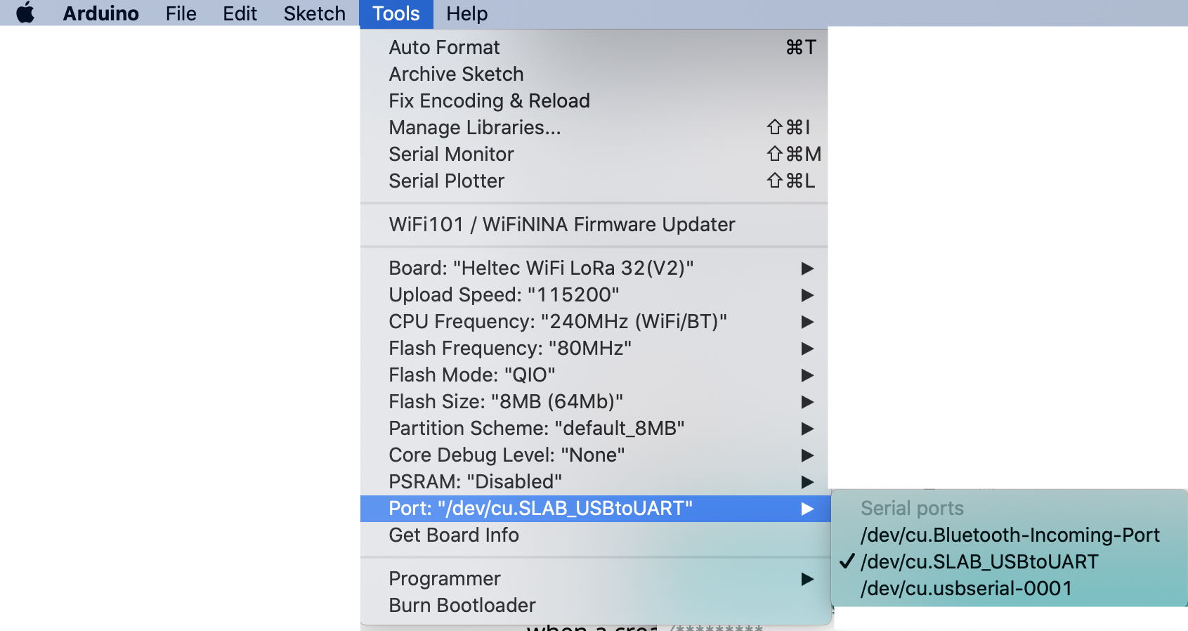
6. Go to “Tools” “Board” “esp32” and select “Helltec Wifi LoRa 32 (v2)”
The pic below is a little confusing because you will notice that “Heltec WiFi LoRa 32(V2)” is already loaded in – but I’m still including this grab so you can see how to select it.
Mouse over where it says “ESP Arduino” and there will be a huge list of boards to choose from. Scroll down near the bottom and select: “Heltec WiFi LoRa 32(V2)”

7. There are drivers you need to install before it will compile properly:
PC drivers are here:
need to list and find these
Mac drivers are here:
need to list these
https://www.silabs.com/products/development-tools/software/usb-to-uart-bridge-vcp-drivers
Esp32 docs here:
https://docs.espressif.com/projects/esp-idf/en/latest/esp32/get-started/index.html
8. There will also be libraries that you need to install, which differ, depending whether you are using a PC or a Mac.
| PC | Mac |
| Link to 2:38 of the youtube tutorial on this | Adafruit GFX Libraries Adafruit Bus LoRa LibrariesNote: You will have to use your system password to unlock your security preferences to install these libraries. (Remember to relock when you’re done :) |
If you’re not sure if you have all the right libraries installed, try to “Open” and “Upload” the software. This will cause the SDK to try to compile the code. You can also go to “Sketch” and then “compile/verify” or (ctrl+R).
If you don’t have all of the correct libraries installed, the names of what you need will be given to you as compile errors in the lower part of the document window. (NEED SCREENGRAB)
Once you have the name, it’s easy to find and install the libraries you need.
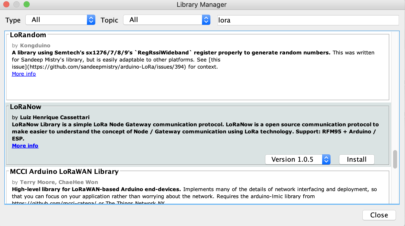
9. Go to “Tools” and then “Manage Libraries” – and search for the library you need using the search box. (You can also scroll down to what you want, but it scrolls very slowly and the libraries aren’t all in alphabetical order! So you’re going to want to use search :)
When you find the library and mouse over it – you will be shown a version drop down menu and an “Install” button.
Select the version you wish to install (use the latest version unless there’s a specific reason not to) and click on “Install.”
10. Select the Port – “Port-dev-cu.SLAB_USBtoUART”
11. Download the zip file of our LoRa software here, and unzip it on your hard drive:
https://github.com/AaronSwartzDay-SSP/LoRa
What’s in our software package:
TREE OF SOFTWARE
12. To load the software on to your esp32, go to “File” “Open” and navigate to the “ino” file in the esp32 directory.
“esp32_wifi_bt_or_gateway.ino”
Creating a Gateway
If you create a gateway, any device connected to your WIFI network can also access the devices on the LoRa network.
To enable the gateway functionality in your pylon, follow these steps. The code is already included in the file, you just need to take out the “//” characters at the beginning of each line that comments it out.
Note that gateway mode must be configured manually and will need an open port on the router.
- remove the “//” in front of “//#define WIFI_IS_CLIENT”
// Uncomment the above to enable use as a gateway.
2. enter the name of your wifi network and its password in this section: (RILEY I could use your help explaining where the different numbers come from below – and how folks look them up for their own networks.)
#define CLIENT_IP_ADDR 192,168,1,200 // client IP address for client or hybrid mode. needs commas instead of periods
#define GATEWAY_IP_ADDR 192,168,1,1 // router IP address for client or hybrid mode. needs commas instead of periods
#define GATEWAY_SUBNET 255,255,255,0 // subnet mask for client or hybrid mode. needs commas instead of periods
#define WIFI_UPSTREAM_AP “NameOfNetworkHere” // SSID of the router we’re trying to connect to.
#define WIFI_UPSTREAM_PWD “PasswordForNetworkHere”// password for the router we’re trying to connect to. Use “” for none/open.
3. Click “Save” – and then “upload” to load the software on to your esp32. (It will say “Hard resetting via RTS pin…” when it’s done.)
To check if the gateway has been configured, press the “PROG” button on the gateway pylon. The address should be what you entered into this chunk of code in step 2 above:
PICTURE of IP ADDRESS on screen of esp32
4. To access the LoRa network over your existing WiFi network using the gateway, type: “192.168.1.200” – into a browser window.
Note that this was the same IP address that you programmed in during STEP 2 above. Here is the code again:
#define CLIENT_IP_ADDR 192,168,1,200 // client IP address for client or hybrid mode. needs commas instead of periods
SCREENGRAB HERE OF ACCESSING 192.168.1.200 over the gateway.
Screengrab here of the messages (a) on screen of #3 esp
Screengrabs here of the messages (a) and (b) on phone 1 & phone 2
Screengrab of Phone 1 with Login as result of captive portal page
Screengrab of Phone 1 with messages (a)
Screengrab of Phone 1 with messages (a) and (b)
Screengrab of Phone 2 captive portal page with messages (c) showing
Cases for your esp32
We have included an .stl file in the /esp32/case folder in the zip file – “lora32_case_edited.stl” – which can be used to 3D print a case that can fit snugly in your pocket or backpack and protect your pylon.
Our case is a modification of the esp32’s “product box” – with rounded edges to better fit in one’s pocket (alas, it is a “pocket pylon”).
A few details for those interested re: 3D printing cases:
When modifying an existing design, it’s important to first make the measurements of the file 1% bigger before modifying it further. This is because whenever you print 3D objects, the filament squishes a teeny tiny bit; but it can be enough to make what you are printing too small to “fit” whatever you are covering.
Another Sidenote: This phenomena of enlarging your blueprints by 1% to account for the squishing phenomena has a corollary for laser cutters, which will always cut your object a teeny bit bigger, to account for the length across of the laser beam doing the cutting.
So for 3D printing – increase your schematic in size by 1%
For laser cutting – decrease your schematic in size by 1% (or to account perfectly for the size of your laser beam).
How to build an Arduino-based pylon and install & configure its software
Arduino set up instructions
Why we created the arduino model:
1) It is a lot cheaper to build
2) It runs on a lot less power – Matteo literally left one running in the dark for three days (so the solar panel wasn’t recharching) and it was still running)
The standard Arduino cellsol node can be used as a repeater, or as an access point for one phone or computer.
A firmware version that has two bluetooth interfaces, and a version that only operates as a repeater but requires less power (and can be airlifted by a cheap drone) also exist; I recommend becoming familiar with the standard version first.
BLOCK DIAGRAM (Logic)
(LoRa transceiver)—-(Arduino)—-(Bluetooth/serial module)
BLOCK DIAGRAM (Power)
Power input —– 3.7v switching reg ——– 3.3v LDO linear reg —- active components
\– battery
POWERING THE NODE
The node is designed to be very tolerant when it comes to input power, so that it can be run in a variety of emergency situations.
The node takes 4 to 6.5V power. You can provide this from USB, a solar panel, or a number of other sources such as:
* USB power bank. It has to be plugged into the USB power input port. You can break down a USB cable to do this and connect the red and black wires.
* 6V lead-acid battery, connected to the USB power input port.
* 6V bike dynamo. Using a diode in series with the node power input is recommended (1N4004 or similar). If you use this, the node MUST have a secondary battery.
* 3 alkaline cells (AAA to D cells) in series. Important: these must be NON-rechargeable!
* Anything that outputs USB (car adapter, wall plug, spare USB port on a wifi router, 10 pounds of potatos connected in series, etc)
* USB hand crank. If you use this, the node MUST have a secondary battery.
Connect the power source to the P+ and P- terminals on the node, or use the micro usb plug. RESPECT POLARITIES. The node does NOT have reverse polarity protection in its current incarnation.
BATTERY TYPES FOR THE NODE
You will need a 3.5 to 4 volt battery to keep the node operating overnight (or when its primary power input is off). The node has been designed to be compatible with a variety of battery typologies. Any one of these will work. If you want to use more than one battery, connect them in parallel. In this case you may NOT mix battery types!
* None. The node has a two stage voltage regulator (switching to 3.7v and linear to 3.3v) and a filter capacitor, so it’s safe to run it without a battery if it has continuous power coming in. The exception, as noted above, is if you have a USB hand crank or bike dynamo.
* 3.7V LiPo battery. Any type is fine (18650, old quadcopter battery, etc). If it has no protection circuit, it’s fine.
* 3.6V lithium battery. Any type is fine (Old cell phone battery, etc).
* 3 rechargeable cells (AAA to D cells) in series. Important: these must be rechargeable!
* 4V lead-acid battery, connected to the battery terminals. Optionally, add a 47 ohm resistor between solar in+ and battery in+. (Note that this also applies to a 6V lead-acid battery that has a dead cell: the node uses little continuous power, so this is safe to do! Good for emergencies.)
* A supercapacitor (if you want to show off) A 5V supercap will work just fine as if it was a battery. Warning: A 3.3V supercap will NOT! If you have one of those, connect it between 3V3 and GND.
* If all you have available is a 3.3V LiFePo4 cell, you can still use it if you connect a capacitor to the battery terminals, and connect the battery itself to the 3V3 and GND terminals on the Arduino. Connect a 47 ohm resistor between B+ on the battery charger board and 3V3. This one is at your own risk and the battery will never get a full charge, but it will work in an emergency.
Connect the battery to the B+ and B- terminals on the node. RESPECT POLARITIES. The node does NOT have reverse polarity protection in its current incarnation. If a battery has other connectors other than + or – you should be able to just ignore them (this is common with cell phone batteries).
Building the Arduino Pylon
You will have to know how to solder in order to build the Arduino pylon from scratch.
I recommend soldering the SX1276 module in first, because it’s the fiddliest part and requires the most focus.
Solder a wire on the base board where the closely spaced holes are, then cut it at about 3mm (1/8in) and let it stick up. Repeat for either all the holes, or if you are in a hurry, the holes that you see a PCB trace coming out of (They are all on the top side of the board except the one near the bluetooth connector). They are 1,4,5,6,7,11, and 12. If you have a proper 1.27mm header, use that instead.
Next, take the SX1276 module, slide into the header you just made, and solder it in place.
The next part that has to go in is the L3338 regulator. Solder it in place. It can only go one way. The large tab isn’t connected to anything, so you can skip it if you are in a hurry; the node doesn’t eat up enough current for the regulator to need a heatsink.
Solder the capacitor and the resistor next. They don’t have a polarity, so it doesn’t matter which way you put them in the board.
Next, solder the Arduino in place, in the same way that you soldered in the SX1276. The holes are more spaced, so it should be easier. If you don’t want to solder and cut wire, you can use a 2.54mm header (also known as a 100 mil header or a 0.1 inch header). In general, if you bought an Arduino Nano or compatible, it should have come with the header. If you are in a hurry, you can only solder the pins you need (GND, 3V3, 0, 1, 7, 10, 11, 12, 13).
Now it’s time to connect the power control board; you will once again have to use the wire-sitting-up trick, or you can use single pegs of a 0.1in header. Place the power control board on the base board so that its USB port is on top, and connect the pins according to where they are on both boards.
B+ and B- go on the JST connector that goes to your battery (or directly to the battery).
P+ and P- go to your solar panel or other non-USB power source (including 6V batteries, do NOT connect a 6V battery to B+ and B-)
OUT+ and OUT- are feeding the node.
The next thing you have to do is solder the antenna to the SX1276. How to do it depends on your antenna. For a simple wire antenna, just solder the GND pin on the far side of the SX1276 to the base board ground, and the ANT pin to a piece of solid (not stranded) wire. I recommend cutting it to 8.5cm (3.5in), soldering it, and then cutting it again so that the part that actually sticks out of the SX1276 is exactly 7.8cm (3.1in) long. Wire length MATTERS since this is an antenna – take some time to measure carefully!
Finally, you have to decide whether you want to permanently solder in the bluetooth to serial module or not (or skip it entirely if you are just making a repeater). Note that if you are soldering in a HC05 or HC06 module, which is the most common module, you will want to connect it so that its SMD board is facing AWAY from the Arduino! If you bend the socket or the module pins to fold it on top of the Arduino, the LED should come up on top.
Upon deploying a repeater with a bare-wire antenna, if you can, the ground pin should go to earth ground, this will improve the radio range.
Loading the Firmware
Now you need to flash the firmware. It’s a regular Arduino sketch, so all you need to do is follow the tutorial that should have come with the Arduino, except that you will be loading the CellSol sketch. You will have to get the Lora.h library from the repository.
The node firmware will work with a 8Mhz Arduino and a 16Mhz Arduino alike; be sure to select the right clock speed in the Arduino IDE. If you get it wrong, nothing will break (so, if you are in doubt, try again with the ohther setting), but the Bluetooth module will not be ble to talk to the Arduino.
If you want to load the firmware with two serial ports, and want to use the second serial port, it will be on pins 8 and 9. You will need a 16Mhz Arduino unless you set the Bluetooth module to operate at 4800bps beforehand.
CONNECTING TO THE PYLON AND SENDING MESSAGES TO IT
You can use either the Arduino serial port programmer to send and receive data from the LoRa mesh, or use the Bluetooth module. For a computer, any serial terminal will work in either case; just set it to 9600bps.
For Android phones, you can download the Bluetooth chat app from an ESP32 CellSol node or get it from us (TODO: Put on android market also).
For iPhone, you will likewise have to find a Bluetooth terminal app.
For Blackberry, S40, S60 and older phones, you CAN use this! Bluetooth terminal apps are available! (For example http://appworld.blackberry.com/webstore/content/59970357 )
The node is pass-through; you will get packets as they come in, and send packets immediately after you hit enter. Unlike the ESP32, it does not have enough memory to hold any message history.
When a packet comes in, you will be told its RSSI, which should give you an idea about how far it’s coming from. This is the RSSI of the last repeater, not of the originating node.
CARE AND FEEDING
The node has no moving parts and will operate pretty much indefinitely on solar power. Be sure that it gets as much sun as possible! Every other year, consider replacing the battery. Every six months or so, clean the solar panel. If you have the whole thing earthed via the ground pin, check for corrosion on the earth peg.